EN
 CN

Automated UV Irradiance Uniformity Measurement with a 104-Point S-Pattern Scan
Product description
Specifications
Download
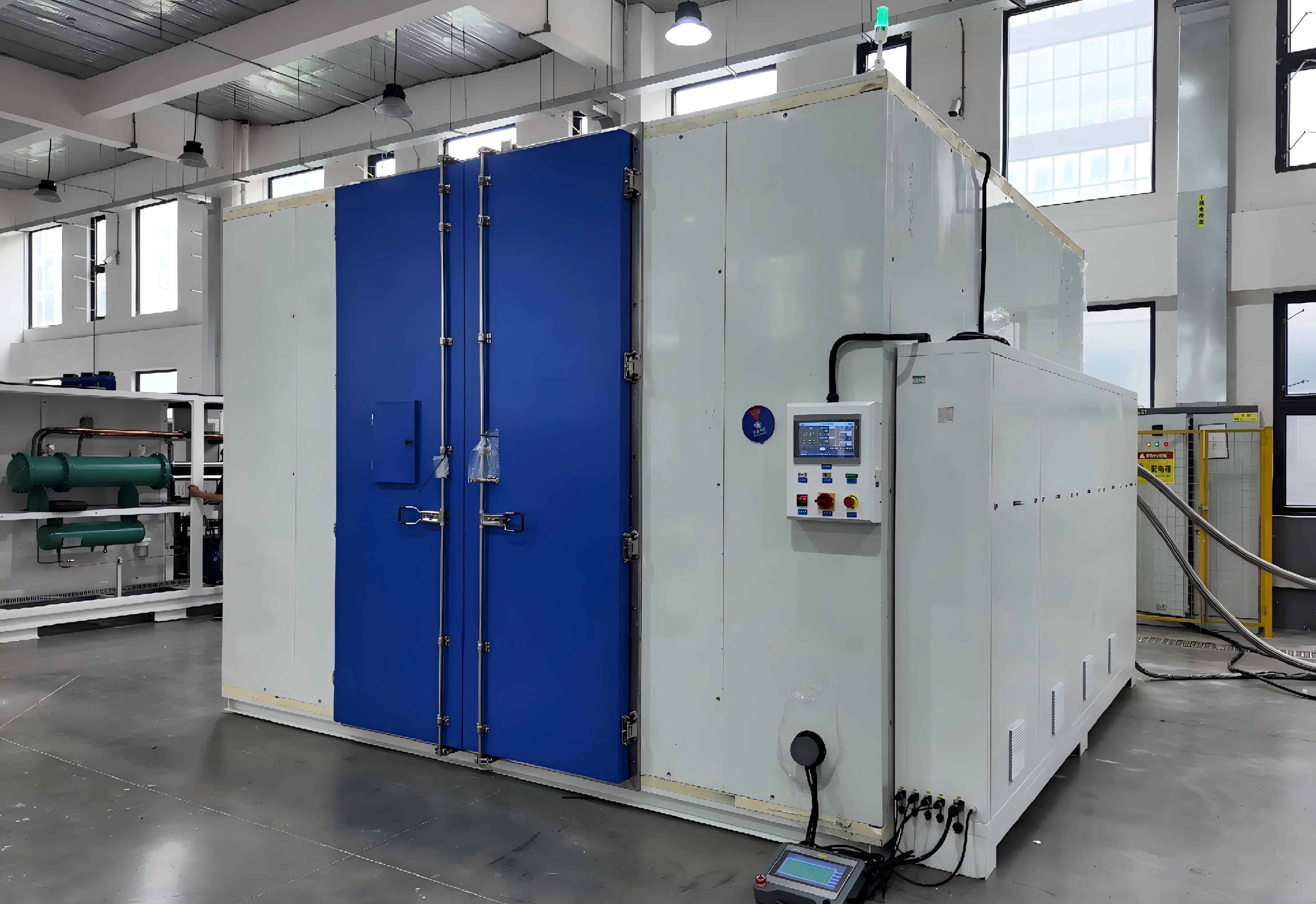
In UV preconditioning tests, PV modules are exposed to a specified UV dose and spectral range to evaluate their resistance to UV degradation.
Before the test begins, however, the laboratory must first confirm an important condition:
Is UV irradiance sufficiently uniform across the entire module test area?
Irradiance non-uniformity can affect test accuracy. It needs to be checked not only during equipment commissioning, but also after the equipment has been operating for some time.
Why Manual Measurement Is More Than a Time Issue
The conventional method relies on manual measurement. An operator moves the radiometer from one position to another, reads the irradiance value at each point and records the data.
This creates several practical difficulties.
Manual positioning offers limited repeatability. The operator must repeatedly move the radiometer, align it with each measurement point and record the result. The process is time-consuming and labour-intensive.
The operator also needs to work close to the UV irradiation area. If adequate protection is not in place, UV exposure may cause injury.
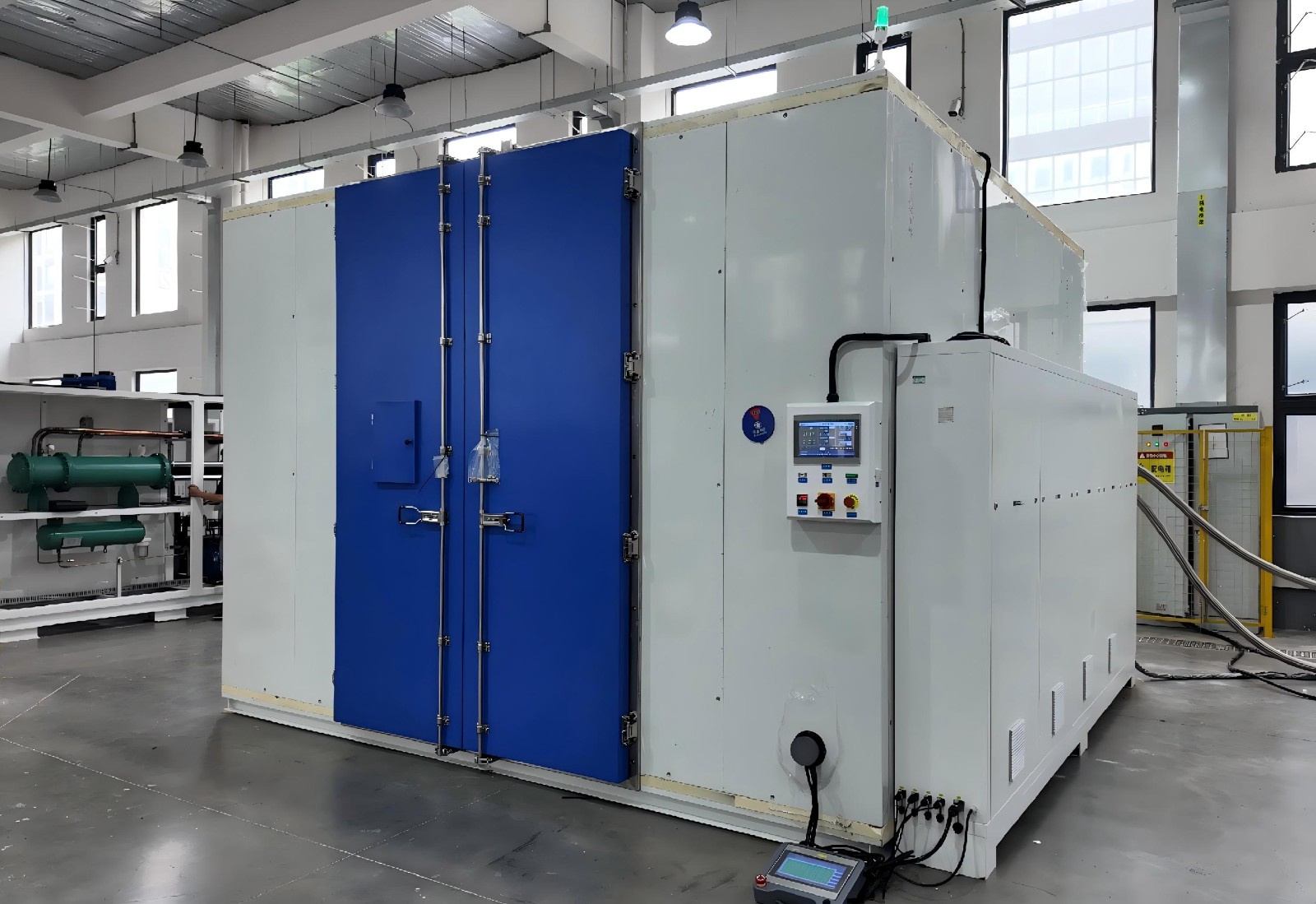
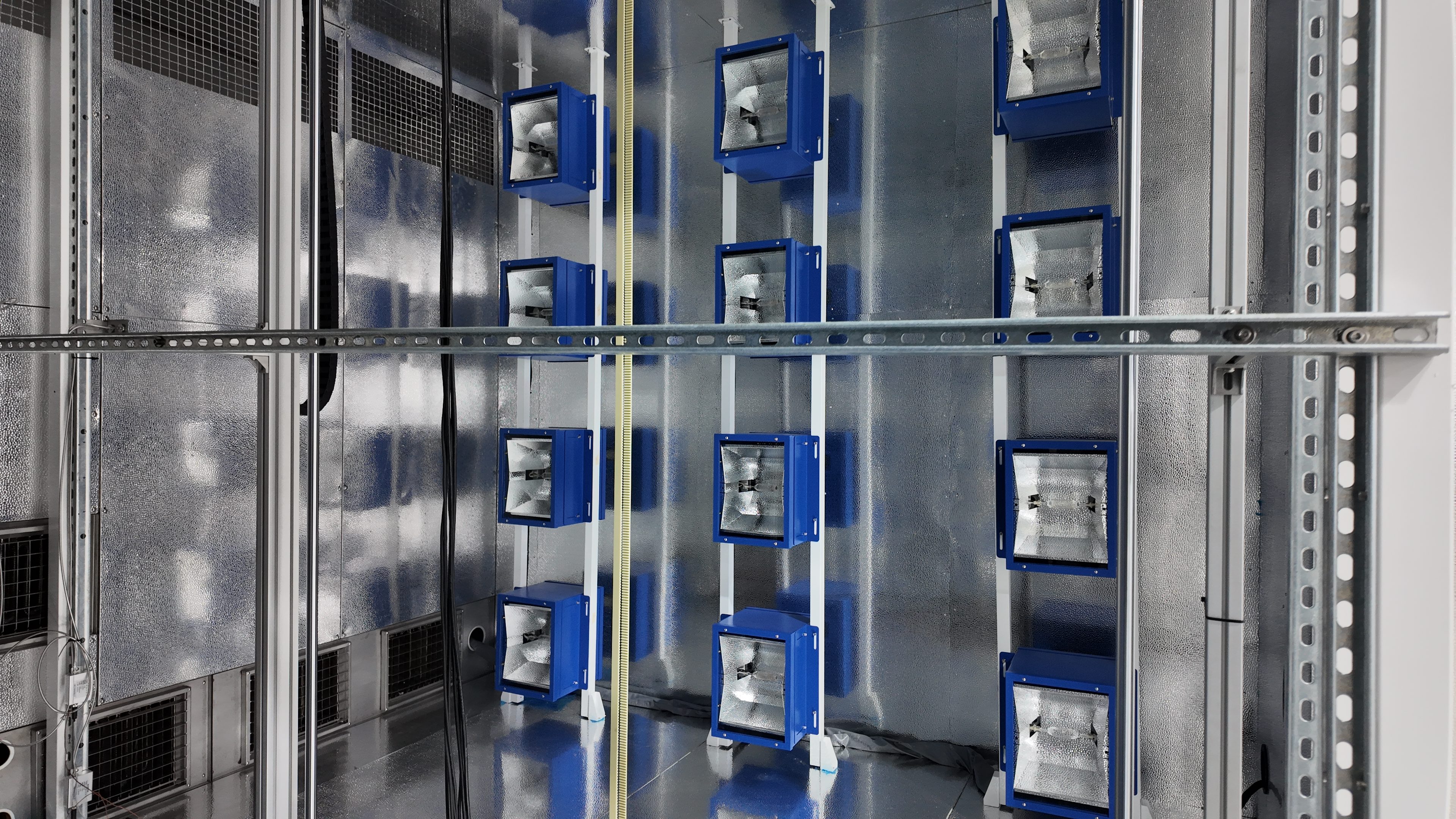
Zealwe recently developed a UV preconditioning chamber with an automated movable measurement system covering the module test area. In this chamber, the UV lamps are arranged vertically, and the PV module is also installed vertically.
This vertical test plane makes manual placement of the radiometer at different positions even more difficult.
For a measurement area of 2600 × 1500 mm, the conventional manual method requires two people and at least two hours.
To address these issues, Zealwe developed a fully automated irradiance non-uniformity measurement system.
A Radiometer That Automatically Covers 104 Measurement Points
The measurement system uses an aluminium-profile frame and a servo-driven positioning mechanism. The transmission structure includes timing pulleys, timing belts and linear bearings, providing a repeat positioning accuracy of ±2 mm.
The travel range can be customized for different PV module sizes and chamber configurations.
Before measurement, the system is fixed in the test area so that the radiometer position corresponds with the target measurement plane. Once the system is secured and powered on, measurement can begin.
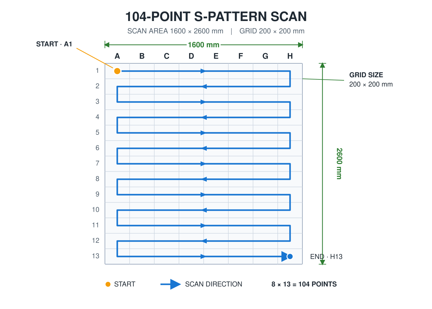
For an effective measurement area of 2600 × 1600 mm, the system divides the area into 104 grids of 200 × 200 mm. The positions are identified by coordinates from A1-A13 through H1-H13.
In automatic mode, the motor first returns to the measurement origin. It then moves the radiometer through the test area along a preset S-pattern path.
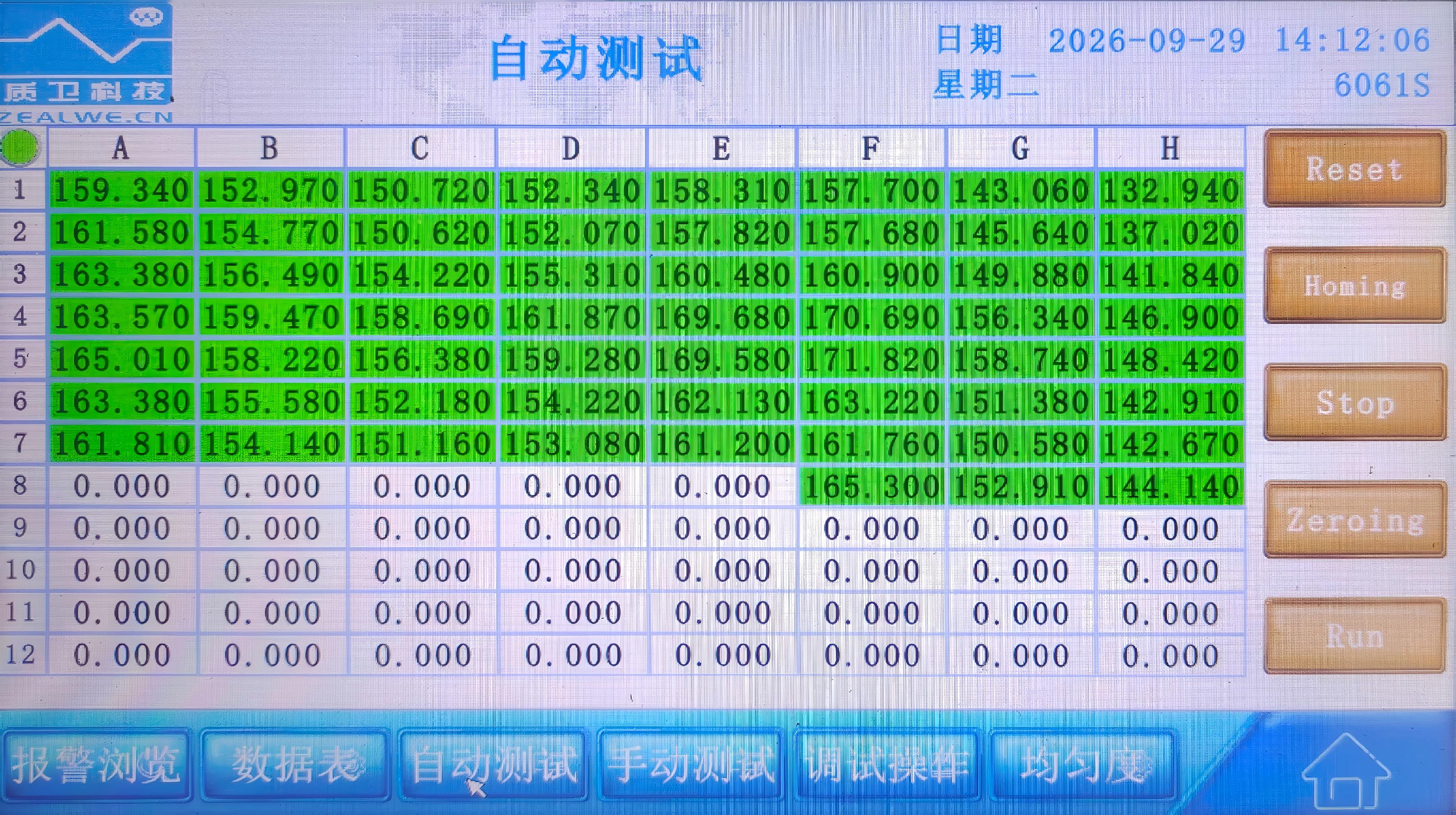
When the radiometer reaches a measurement position, the corresponding grid on the touchscreen turns green. The system remains at the point for two seconds, collects the irradiance value, displays and retains the data in the corresponding grid, and then moves to the next position.
No manual repositioning or point-by-point data recording is required during the scan.
After all 104 points have been measured, the operator selects the non-uniformity calculation function. The system identifies the maximum value in red and the minimum value in yellow, then calculates irradiance non-uniformity using the following formula:
Irradiance non-uniformity = (Maximum value - Minimum value) ÷ (Maximum value + Minimum value) × 100%
The manual process previously required two people and at least two hours. With the automated system, data from all measurement points and the final non-uniformity result can be obtained in about 10 minutes after setup and test initiation.
Automatic and Manual Measurement Modes
The system provides both automatic and manual modes.
In automatic mode, the radiometer follows the complete S-pattern path, collects the data at each point and supports the final non-uniformity calculation.
In manual mode, the operator can select an individual point on the touchscreen. The motor moves the radiometer to that position, remains there for two seconds and displays the irradiance value.
Manual mode is intended for checking selected positions. It displays individual irradiance values but does not calculate overall irradiance non-uniformity.
From FAT to Periodic Uniformity Checks
During equipment commissioning, irradiance non-uniformity measurement helps the laboratory adjust the UV preconditioning chamber to meet the FAT requirements specified in the technical agreement.
The measurement remains important after equipment delivery.
As UV lamps and reflectors age, irradiance non-uniformity may increase. Periodic measurement allows the laboratory to identify changes and adjust the equipment according to the results, helping maintain accurate test conditions.
The system is applicable to UV preconditioning tests involving:
IEC 61215 MQT 10
IEC 61730 MST 54
IEC 63126
The equipment is designed to meet the UV preconditioning test conditions specified in IEC 61215-2:2021 MQT 10. The irradiation area can be designed according to project requirements.
By replacing repeated manual positioning and recording with an automated 104-point scan, the system makes irradiance uniformity checks faster and more practical during both FAT and long-term laboratory operation.
- File name Release date Ooperating