The Art of Harnessing Wind: From Turbine to Volute – The Core of Aerodynamics in Test Equipment
Product description
Specifications
Download
The Art of Harnessing Wind: From Turbine to Volute – The Core of Aerodynamics in Test Equipment
This paper examines the pivotal role of aerodynamic optimisation in environmental test equipment, exploring three key dimensions: fans, volutes, and ductwork, while drawing upon engineering case studies.
Preface:
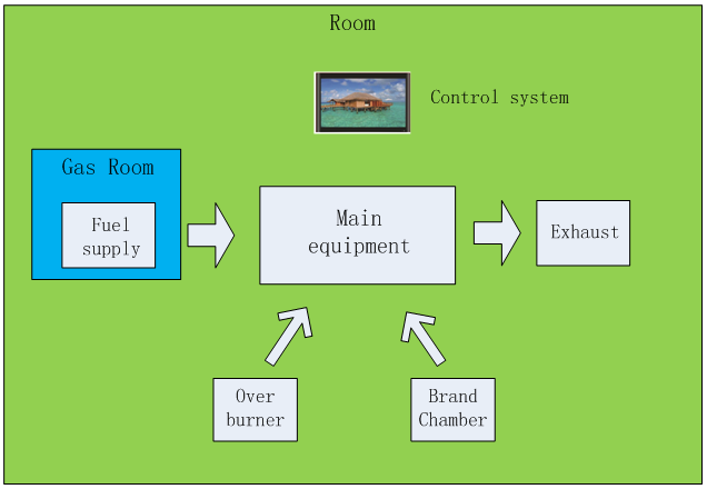
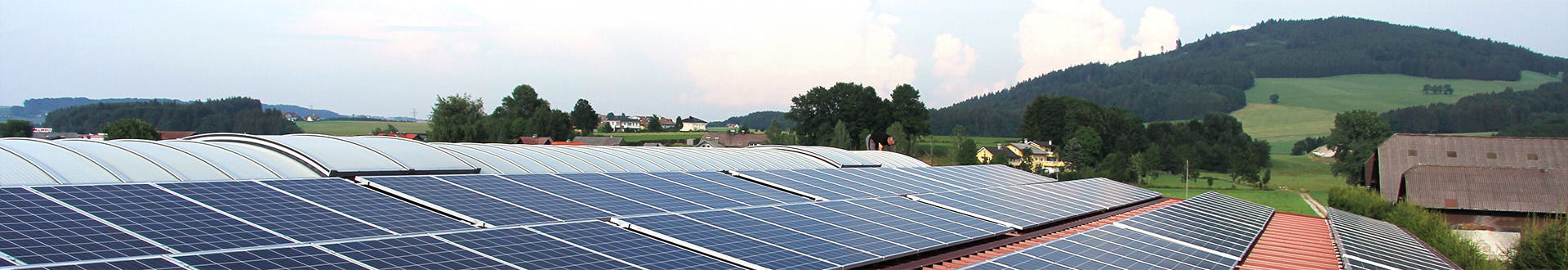
Environmental chambers are a crucial means of environmental simulation, and their application is indispensable during solar panel testing. Due to the specific dimensions of solar panels, these chambers are relatively large in size. If the airflow system is poorly designed, the rate of temperature change and temperature uniformity within the chamber cannot be adequately controlled, thereby compromising test results.
During the design and development of environmental testing equipment, aerodynamic factors are often underestimated. Traditional approaches predominantly focus design efforts on refrigeration system capacity and electric heating configurations, assuming that sufficient cooling and heating capacity alone guarantees equipment performance.
However, extensive engineering practice demonstrates that refrigeration and heating capacity are not the decisive factors. The root causes of issues such as uneven temperature field distribution, reduced temperature control efficiency, and high energy consumption often stem from the irrational organisation of internal airflow within the equipment.
Fans, volutes, and ductwork form the core of aerodynamic design in test equipment. These components not only determine airflow circulation efficiency but also directly influence temperature uniformity, energy consumption levels, and noise characteristics.
This paper explores the critical role of aerodynamic optimisation in environmental test equipment through three dimensions—fans, volutes, and ductwork—illustrated with engineering case studies.

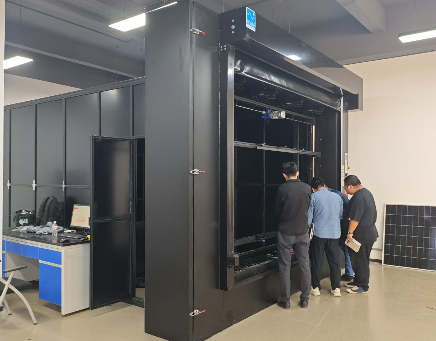
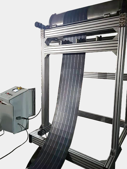
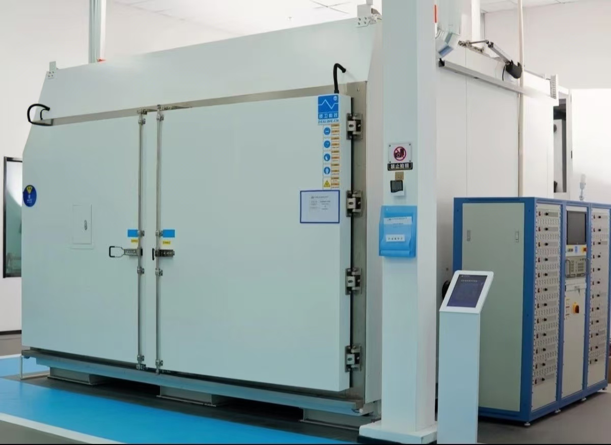
The high-low temperature and humidity freeze test chamber manufactured by ZZealwe Technology for testing multiple solar modules complies with IEC 61215 standards: MQT11 for high-low temperature cycling and MQT12 for humidity freeze testing. At full load, it achieves a temperature change rate of 3.3°C/min with temperature uniformity of ±2°C. When integrated with our proprietary current continuity system, it becomes an indispensable tool for photovoltaic module testing.
2. Design Approach
Fan: The Powerhouse
The fan serves as the air circulation power source for environmental test chambers, with its performance directly determining airflow delivery capacity and circulation efficiency.
During design, the equipment's resistance characteristic curve must be matched with the fan's static pressure-airflow characteristic curve to ensure the fan operates within its high-efficiency range.
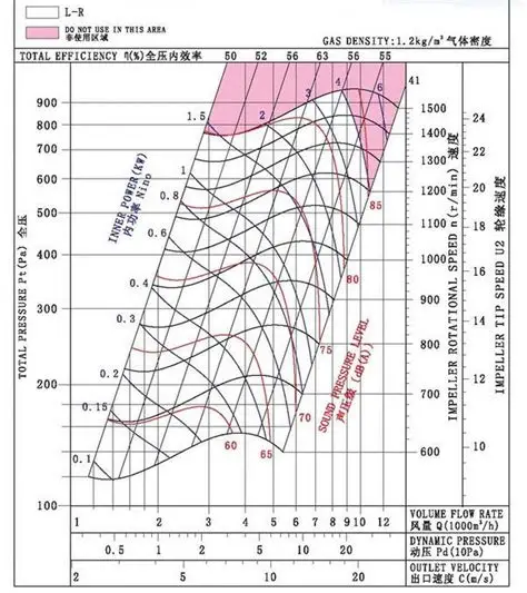
• Axial flow fans: Suitable for applications with low system resistance, offering high airflow but limited static pressure.
• Centrifugal fans: Characterised by high static pressure and adaptability to complex ductwork, widely employed in test chambers with rapid temperature changes and large dimensions.
It should be noted that increased airflow does not necessarily improve temperature uniformity. Uneven velocity distribution or the formation of localised high-speed zones may instead increase temperature gradients and elevate noise levels. Consequently, fan selection involves not merely power considerations, but also efficiency and flow field compatibility.
Volute: Energy Converter
The volute serves as the critical component converting kinetic energy at the impeller outlet into static pressure. Its geometric parameters directly influence flow field stability and energy utilisation efficiency.
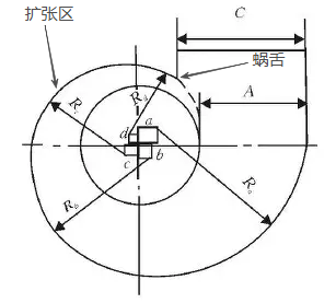
• The volute tongue angle determines fluid impact intensity and secondary flow losses;
• The expansion ratio influences the airflow diffusion process; excessive expansion causes separation and vortex formation, while insufficient expansion increases volume and cost;
• The outlet cross-sectional shape affects flow field distribution; an overly small cross-section creates localised high velocities, while an excessively large one results in insufficient static pressure.
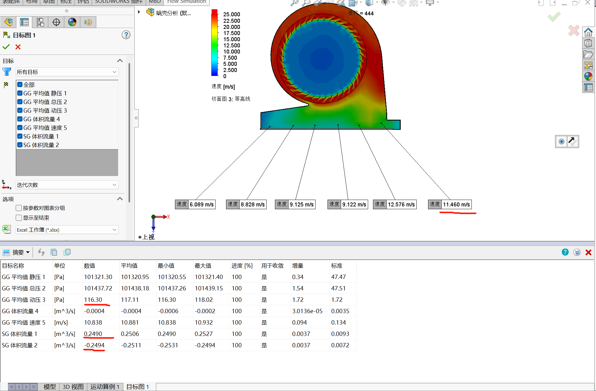
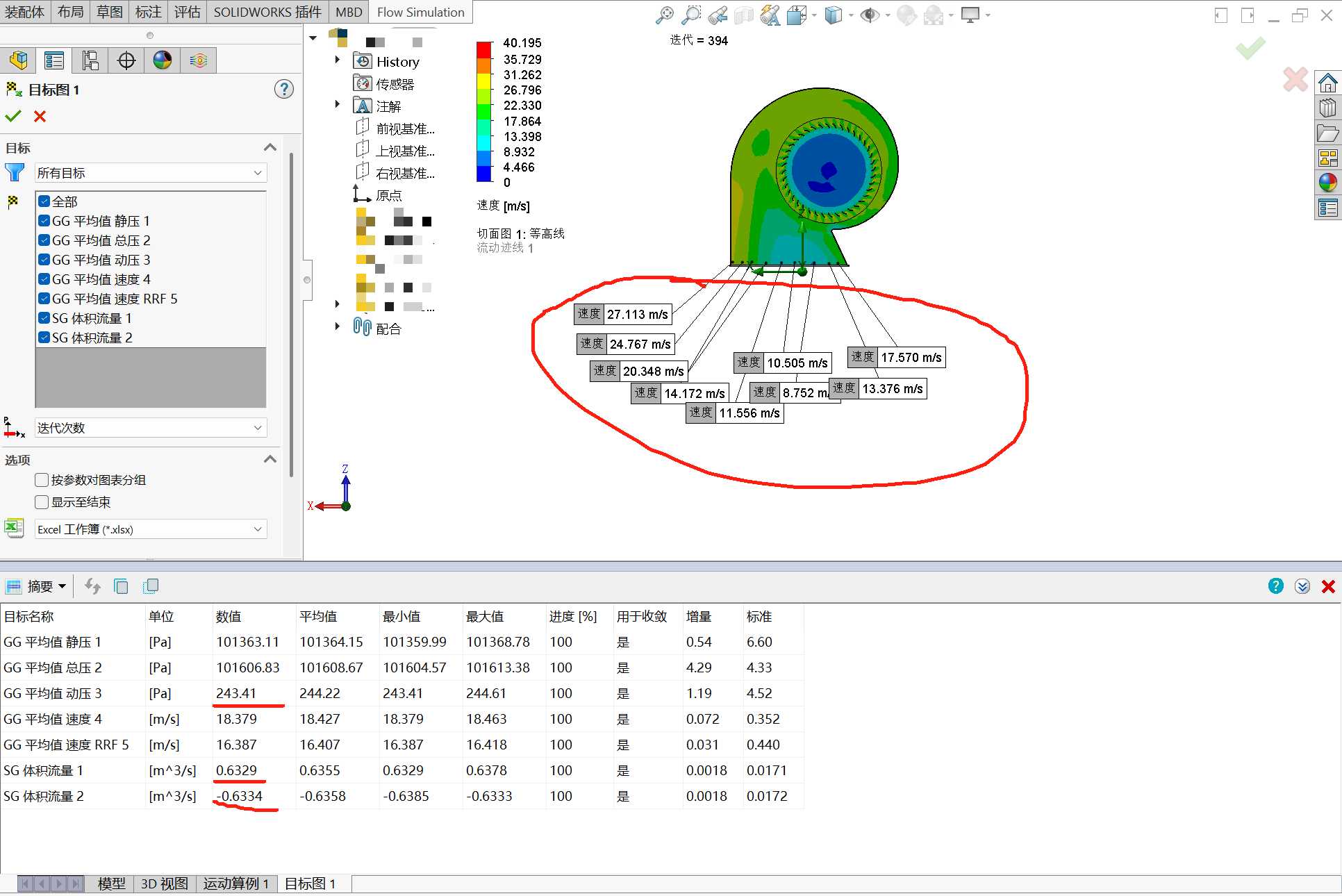
During the design phase, volute design relies not only on empirical formulas but also requires validation of internal flow patterns through CFD numerical simulation. Analysis of streamlines, pressure fields, and velocity fields enables the identification of potential energy loss zones, allowing for corrective measures during the design stage.
Air Ducts: The Highways for Air
Air ducts serve as the conduits for airflow organisation, where their rational layout directly determines temperature uniformity and heat transfer efficiency.
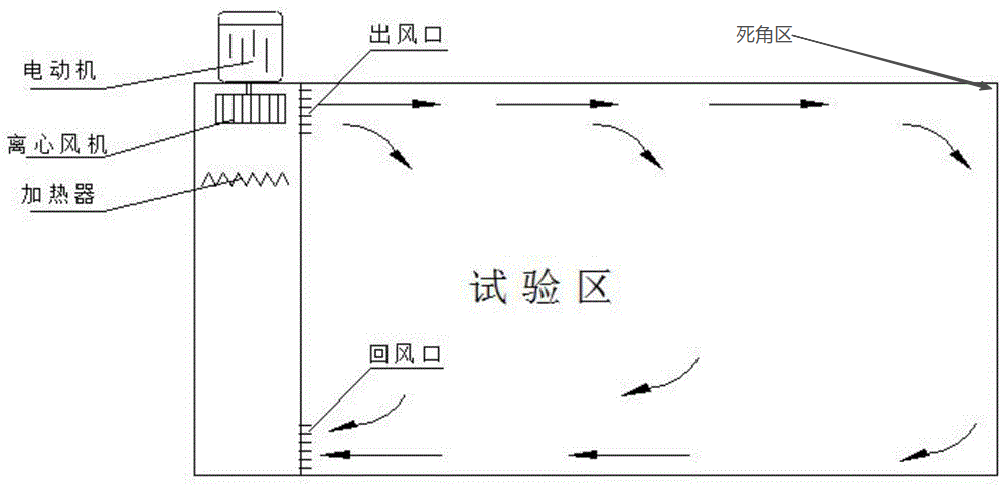
• Circulation mode: Common configurations include single-loop and dual-loop structures, with the latter offering superior temperature uniformity control for larger units;
• Return/supply air ratio: A well-designed return air system mitigates short-circuiting risks and ensures comprehensive airflow coverage of the working space;
• Cross-sectional variation control: Avoid abrupt constrictions or expansions to maintain Reynolds number and pressure drop within controllable ranges.
During design, CFD simulations may be employed to evaluate velocity and temperature fields, identifying dead zones and short-circuiting areas. These numerical models should be calibrated through prototype testing to achieve greater predictive accuracy and optimisation efficiency.
3. Application Cases
3.1 Enhanced Temperature Change Rate
Background: In the initial design of the first-generation rapid thermal cycling environmental test chamber, despite incorporating a high-power centrifugal fan, actual testing revealed that the equipment's linear cooling rate in the low-temperature range (-40°C) was only approximately 2.6°C/min. This failed to meet the requirements of IEC 61215:2021 for the ‘Thermal Shock Test’ of photovoltaic modules. at low temperatures was only approximately 2.6 °C/min, failing to meet the ≥3.3 °C/min requirement stipulated in IEC 61215:2021 for the ‘Thermal Cycling Test’ of photovoltaic modules.
Problem Review:
• The fan provides sufficient thrust, but the volute is undersized, resulting in inadequate efficiency in converting kinetic energy to static pressure. This leads to low airflow utilisation within the heat exchanger.
• Abrupt changes in duct cross-section create localised backflow and low-velocity zones, diminishing overall heat transfer efficiency.
Optimisation Measures:
• Adjust the volute expansion ratio and volute tongue angle to enhance kinetic-to-static pressure conversion efficiency;
• Optimise the duct transition section to reduce airflow separation and localised backflow, thereby improving airflow coverage across the evaporator surface.
Results:
• Cooling performance has been significantly enhanced, with the linear cooling rate increasing from approximately 2.6 °C/min to 3.4 °C/min, meeting specification requirements;
• System operation is more stable, with improved heat exchange efficiency at low temperatures;
• Energy consumption has been reduced by approximately 10%, and noise levels have been mitigated.
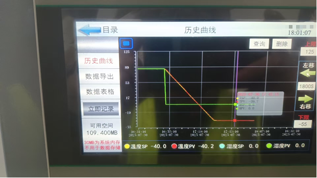
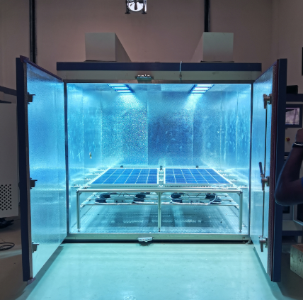
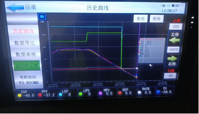
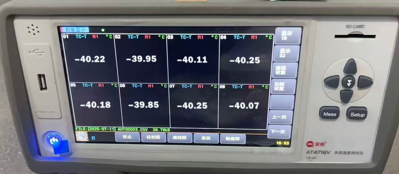
3.2 Improvement in Temperature Uniformity
We tested the temperature uniformity, as shown in the figure below.
4. Conclusion
This case demonstrates that optimising aerodynamic design directly impacts the cooling rate and system efficiency of environmental test chambers.
Aerodynamic design constitutes a critical element in performance optimisation.
The ultimate objective of environmental testing equipment is to achieve stable, uniform, and controllable environmental conditions under specified operating conditions. Achieving this goal relies not only on rational refrigeration and heating configurations but, more crucially, on the reliability and precision of aerodynamic design.
Fans provide the airflow momentum, volutes accomplish energy conversion, and ductwork organises flow paths. The interplay between these three elements determines temperature field distribution and energy efficiency levels. Neglecting this aspect often results in equipment exhibiting ‘sufficient power but inadequate performance’.
In practical design, aerodynamic optimisation is not a singular measure but a systematic engineering endeavour, requiring consideration of multiple constraints including efficiency, noise, space, and manufacturing processes.
Through rational computation, simulation, and experimental validation, dual optimisation of temperature uniformity and energy consumption can be achieved while maintaining controllable equipment volume and cost.
Mastering aerodynamics demands relentless refinement. In the long term, precision aerodynamic design represents not only a technical pathway to enhance equipment performance but also a core competitive advantage for enterprises seeking differentiation and future success.
Author Profile
Wang Chao
With a decade of experience in the photovoltaic industry, Wang Chao has specialised in the structural design and optimisation of environmental test chambers. He excels in resolving complex design challenges through structural innovation and process refinement.
He has spearheaded the mechanical design and process optimisation of diverse equipment, including high/low-temperature chambers, humidity/heat chambers, and light exposure systems. His efforts have consistently enhanced reliability and assembly efficiency.
Moving forward, he will lead his team in advancing equipment towards greater precision and intelligence, delivering superior solutions for industry clients.
- File name Release date Ooperating