Why Many Environmental Chamber Issues Are Actually Airflow Problems
Product description
Specifications
Download
Why Many Environmental Chamber Issues Are Actually Airflow Problems
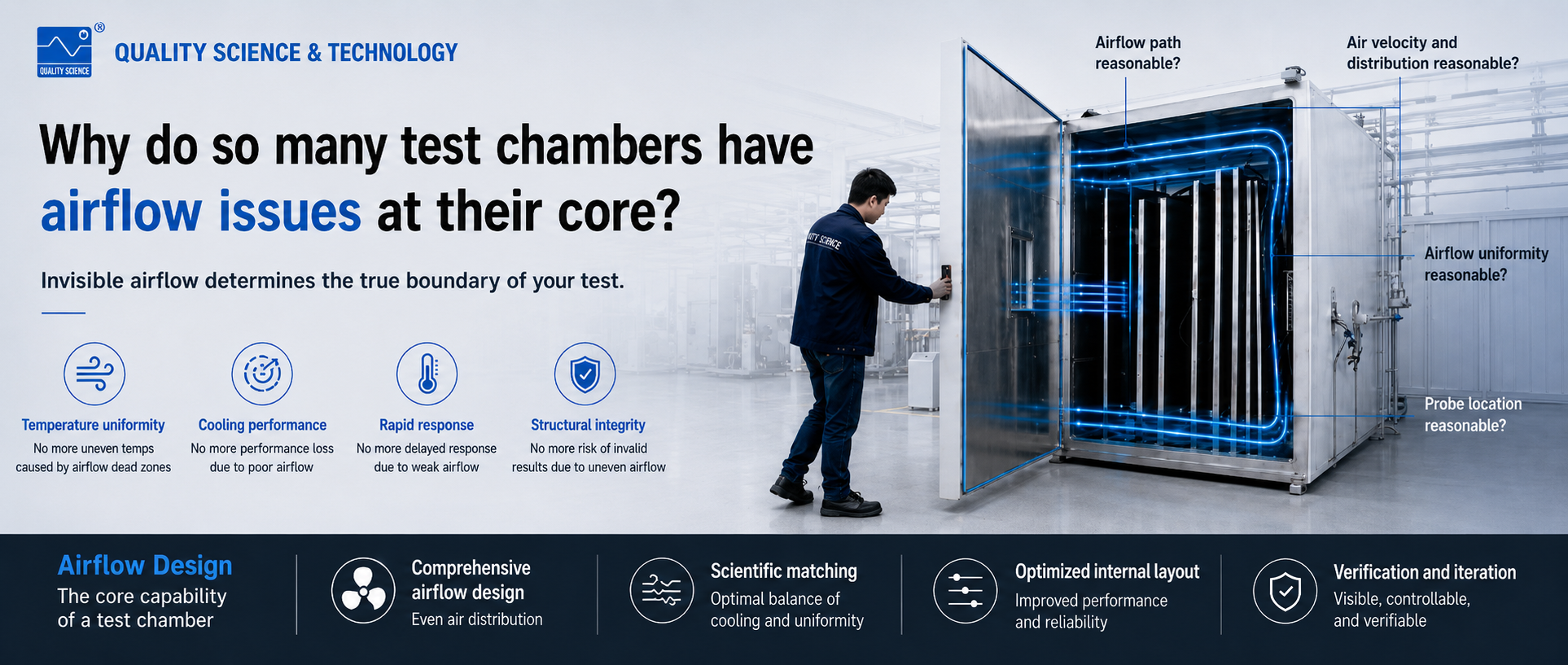
Understanding Temperature Uniformity, Cooling Performance and Airflow Organization
Introduction
During environmental chamber commissioning and long-term operation, many issues initially appear to be temperature-related.
However, when engineers trace the root cause, they often discover that airflow organization is the real factor behind the problem.
Typical examples include:
- Chambers performing well under no-load conditions but showing delayed temperature response after large samples are installed.
- Rapid cooling at the beginning of a test, followed by a significant reduction in cooling rate later.
- Systems with seemingly sufficient airflow volume but poor temperature response in specific areas.
Although these issues appear to be temperature problems, they are often caused by ineffective airflow coverage and insufficient air renewal in critical regions.
Airflow and the Cooling Process
The cooling process of an environmental chamber can be simplified as follows:
The more heat removed per unit time, the faster the temperature decreases.
In practice, heat is first transferred from the specimen and chamber structure to the surrounding air. The moving air then carries that heat away.
Therefore, airflow directly affects cooling performance.
At any location inside the chamber, the cooling rate depends largely on local heat-transfer conditions.
Areas receiving sufficient airflow experience:
- Faster air renewal
- Better heat transfer
- Faster temperature response
Areas with restricted airflow tend to exhibit:
- Slower heat exchange
- Delayed cooling
- Larger temperature deviations
Because airflow distribution is never perfectly uniform, low-velocity regions often develop near:
- Chamber corners
- Obstructed areas
- Sample shadow zones
- Downstream regions behind large specimens
These regions frequently become the limiting factor for overall chamber performance.
This is why engineers often observe:
- Fast cooling at the beginning of a test
- Slower cooling later in the cycle
Long-term lagging of individual measurement points
Why Increasing Airflow Does Not Always Solve the Problem
Increasing fan speed is often the first solution considered during troubleshooting.
However, if the root cause lies in:
- Poor airflow paths
- Premature return-air circulation
- Persistent low-flow regions
then simply increasing airflow volume may not fully solve the problem.
Air naturally follows the path of least resistance.
When airflow volume increases, the main airflow channels often become stronger, while low-flow regions remain largely unaffected.
As a result:
More airflow does not necessarily mean better airflow distribution.
The key question is not whether air is moving, but whether it actually reaches the locations where heat transfer is required.
How Airflow Distribution Is Formed
Airflow distribution is not created naturally inside the chamber.
Instead, it is determined by several interacting factors:
- Fan driving force
- Air duct design
- Resistance distribution
- Evaporator characteristics
- Return-air structure
Together, these elements form a complete airflow network.
The fan provides energy, but it does not directly determine how airflow is distributed throughout the working area.
Once airflow enters the system, it naturally concentrates in paths with lower resistance.
Without proper control, some areas receive excessive airflow while others receive very little.
The Role of Air Ducts
Air ducts define where airflow can travel.
Their primary purpose is to establish continuous circulation paths and ensure airflow reaches all required regions.
Even when total airflow volume is sufficient, poor duct design can leave certain regions permanently under-ventilated.
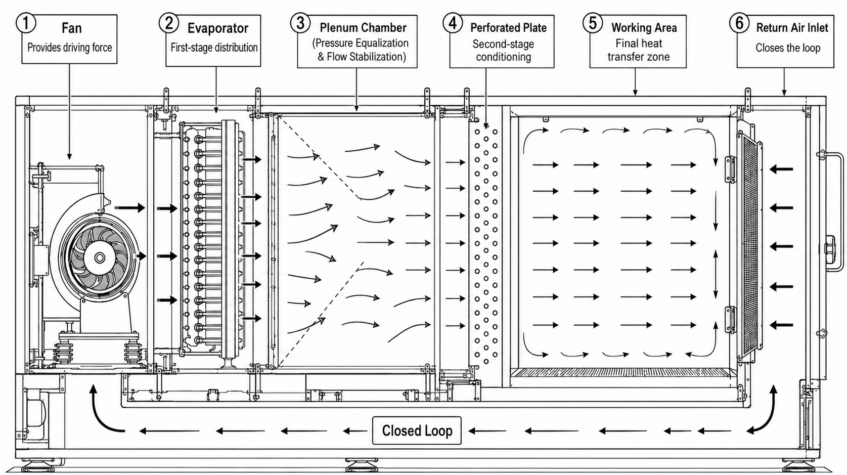
The Role of the Evaporator
The evaporator is often one of the largest resistance sources within the airflow system.
As airflow passes through the evaporator, it experiences:
- Velocity variations
- Directional changes
- Pressure differences
This becomes the first stage of airflow distribution.
Subsequent structures such as:
- Plenum chambers
- Perforated plates
- Air diffusers
- Flow-guiding components
perform a second stage of airflow redistribution before air enters the working area.
Therefore, airflow behavior observed inside the chamber is usually the combined result of multiple distribution stages rather than a single structural element.
Conclusion
The purpose of airflow analysis is not to simply conclude that airflow volume is insufficient.
More importantly, it helps determine whether airflow:
- Reaches the target area
- Maintains continuous circulation
- Provides effective local air renewal
In many cases, these factors are far more important than nominal airflow volume.
In the next article, we will explore how airflow is intentionally shaped and controlled through structural design, including air ducts, perforated plates, return-air systems and airflow management strategies.
- File name Release date Ooperating