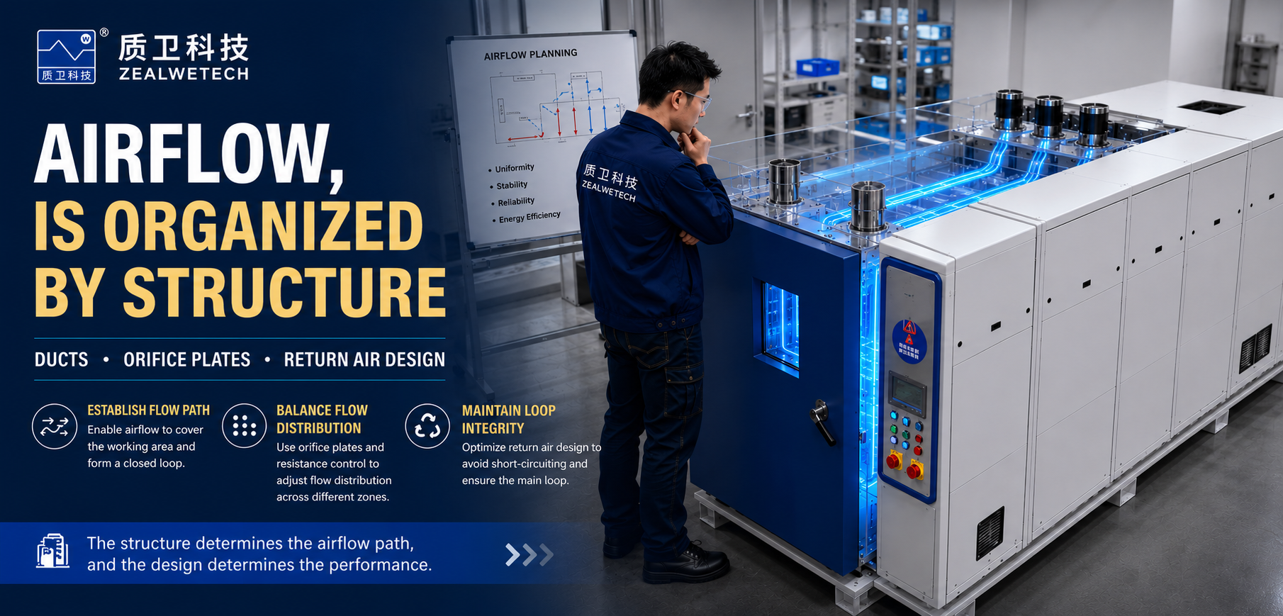
How Airflow Is Organized Inside an Environmental Chamber
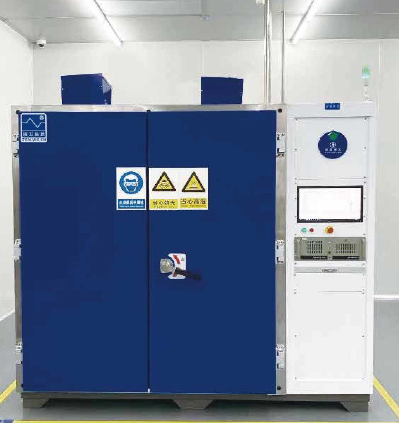
Product description
Specifications
Download
How Airflow Is Organized Inside an Environmental Chamber
Understanding Airflow Control Through Structural Design
Introduction
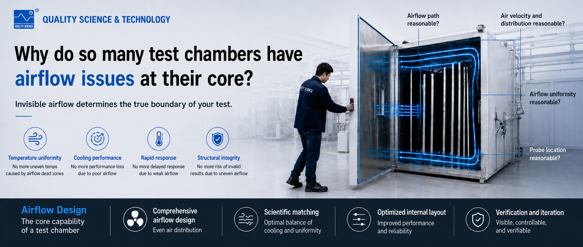
In the previous article, we discussed how many chamber performance issues originate from airflow distribution rather than temperature control itself.
This article focuses on the structural side of airflow organization.
Airflow does not naturally distribute evenly throughout a chamber.
Instead, it is shaped by:
- Air ducts
- Perforated plates
- Return-air structures
- Resistance relationships
- Internal components
Together, these elements determine how air moves through the chamber.
Structural Control of Airflow
Airflow control is essentially the control of:
- Flow paths
- Resistance distribution
Since airflow naturally prefers low-resistance routes, the objective is not simply to increase velocity.
The real goal is to create relatively uniform airflow conditions throughout the working area.
Effective airflow design begins during the structural design stage rather than through later corrective actions.
Establishing Airflow Paths
The first task is to establish complete airflow circulation paths.
Air ducts and return-air structures ensure that airflow:
- Covers the working area
- Forms a closed circulation loop
- Reaches all required regions
If airflow paths are incomplete or prematurely closed, later adjustments become difficult.
Managing Airflow Distribution
Once airflow paths are established, airflow distribution must be controlled.
Because airflow automatically follows resistance differences, designers can intentionally use resistance elements to redistribute airflow.
Common methods include:
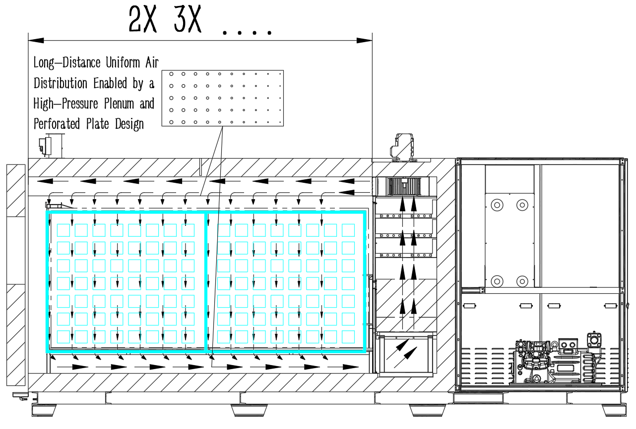
- Perforated plates
- Air diffusers
- Plenum chambers
The purpose is not to force identical airflow everywhere, but to provide airflow according to local heat-transfer requirements.
Airflow Control Methods in Chamber Design
In practical engineering projects, airflow control generally follows three approaches.
1. Flow Path Organization
Examples include:
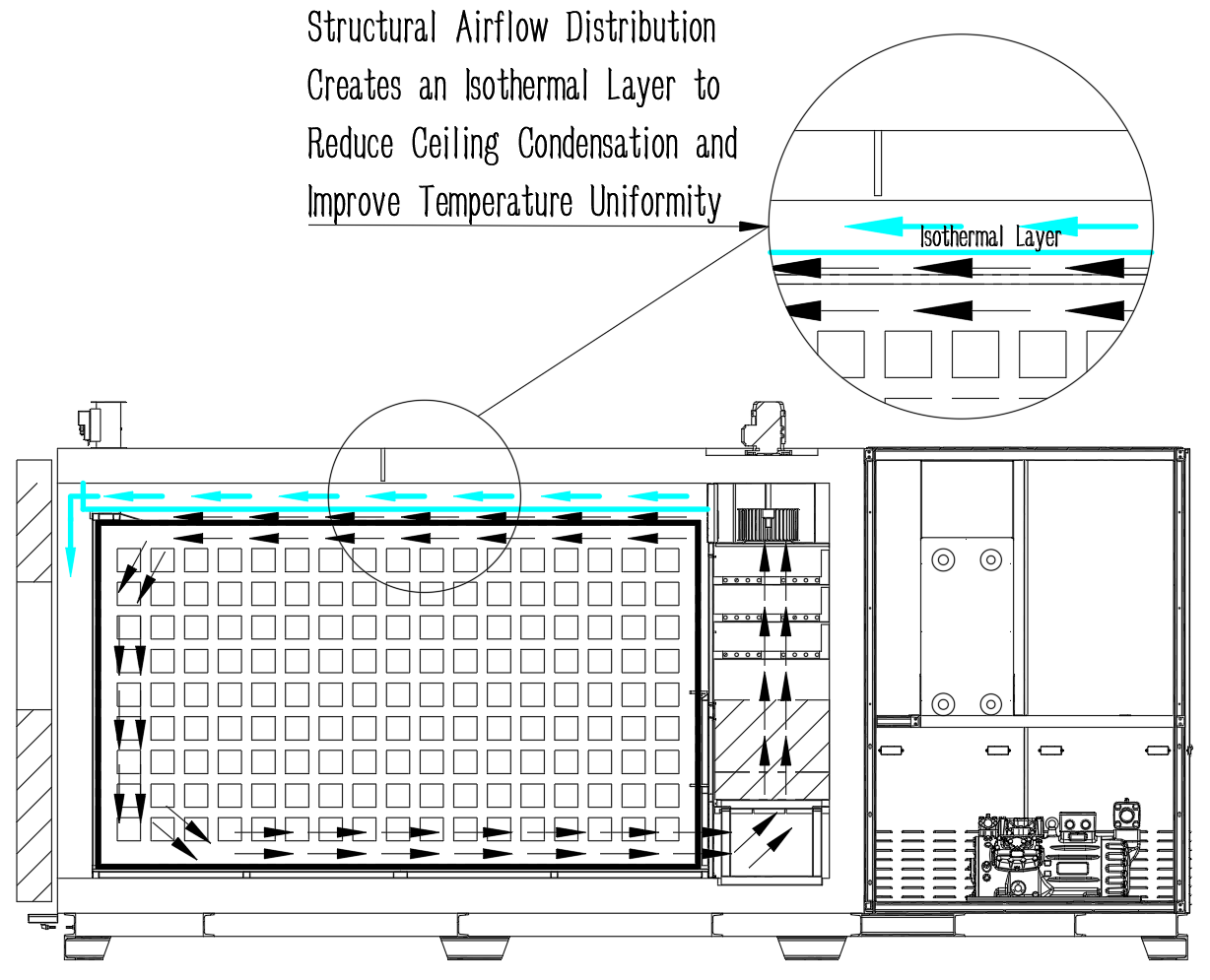
- Air distribution layers
- Wall-guided airflow
- Dual-duct systems
- Symmetrical supply and return-air arrangements
These structures help organize airflow before it enters the working area.
Their purpose is to improve coverage and circulation balance.
2. Flow Equalization
When airflow enters the chamber with strong directional bias, additional redistribution becomes necessary.
This is commonly achieved through:
- Plenum chambers
- Zoned perforated plates
Plenum chambers stabilize airflow conditions.
Perforated plates adjust local resistance to improve airflow uniformity.
3. Resistance Compensation
Airflow performance depends not only on having airflow channels, but also on how efficiently airflow can move through them.
Typical optimization methods include:
- Rounded transitions instead of sharp corners
- Variable cross-section ducts
- Reduction of sudden expansions and contractions
These measures reduce:
- Pressure losses
- Recirculation zones
- Turbulence losses
and improve overall airflow efficiency.
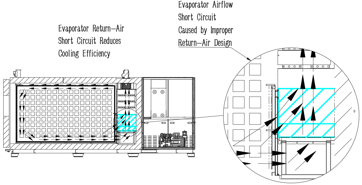
The Importance of Return-Air Design
Return-air design is often overlooked.
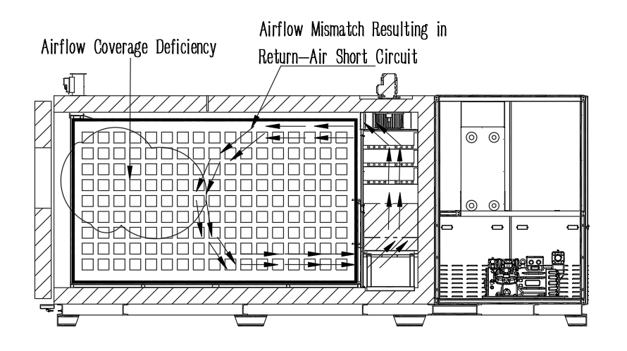
If the return-air path is too short or poorly positioned, airflow may return before adequately covering the working area.
This creates a short-circuit airflow loop.
In many cases, such problems cannot be solved simply by increasing airflow volume.
Preventing airflow short-circuiting is therefore a fundamental design requirement rather than an optional optimization.
Conclusion
Effective airflow control is not a repair method applied after problems appear.
Instead, it is a design strategy that should be considered from the earliest stages of chamber development.
Successful airflow design requires coordinated planning of:
- Airflow paths
- Resistance relationships
- Circulation loops
- Internal layouts
Only when these elements work together can a chamber achieve stable, predictable and repeatable thermal performance.
In the next article, we will examine why many airflow-related issues become difficult to fully resolve during commissioning, and how CFD simulation can help identify risks before manufacturing begins.
- File name Release date Ooperating